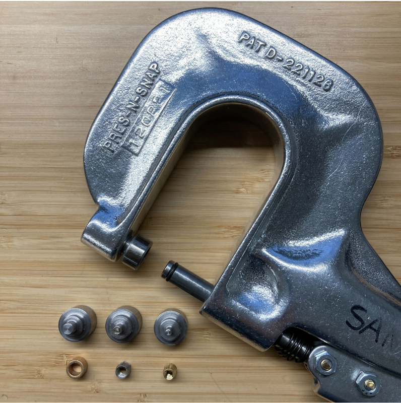
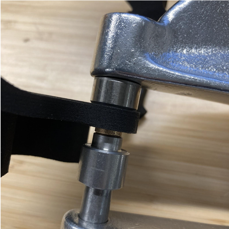
created custom tooling on lathe for pressing in threaded inserts and brass bushings
made drawings of aluminum parts for vendor
created assembly documentation
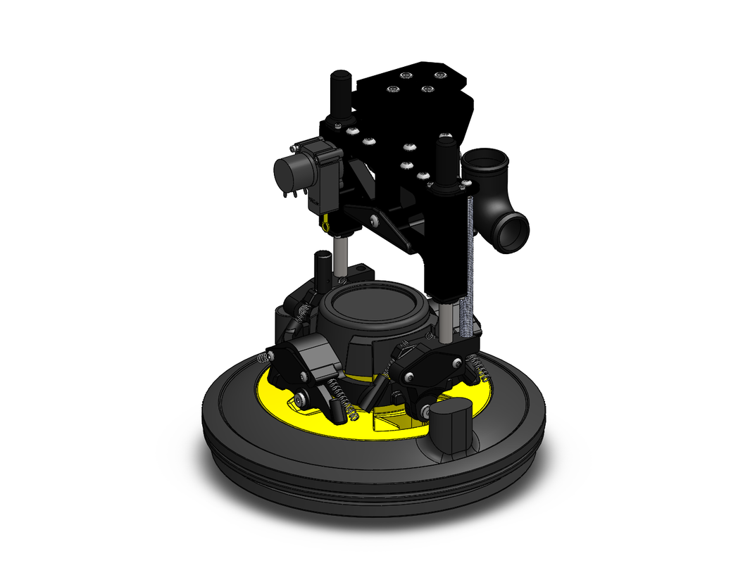
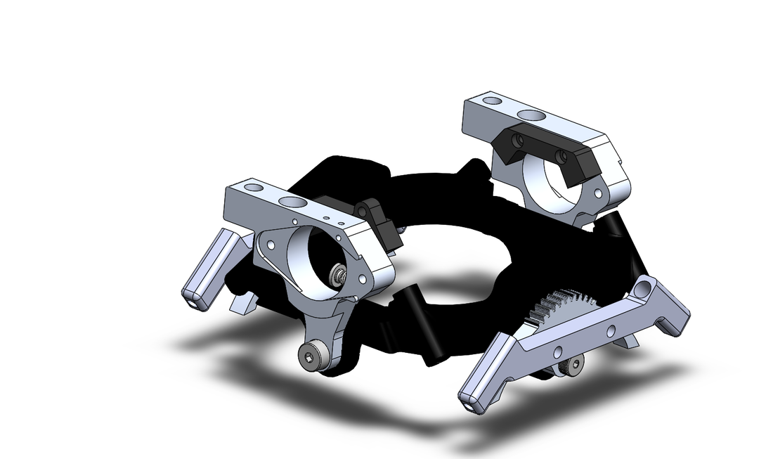
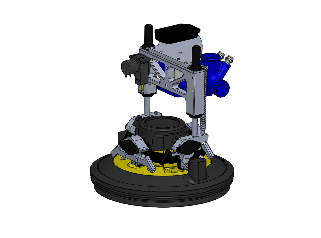
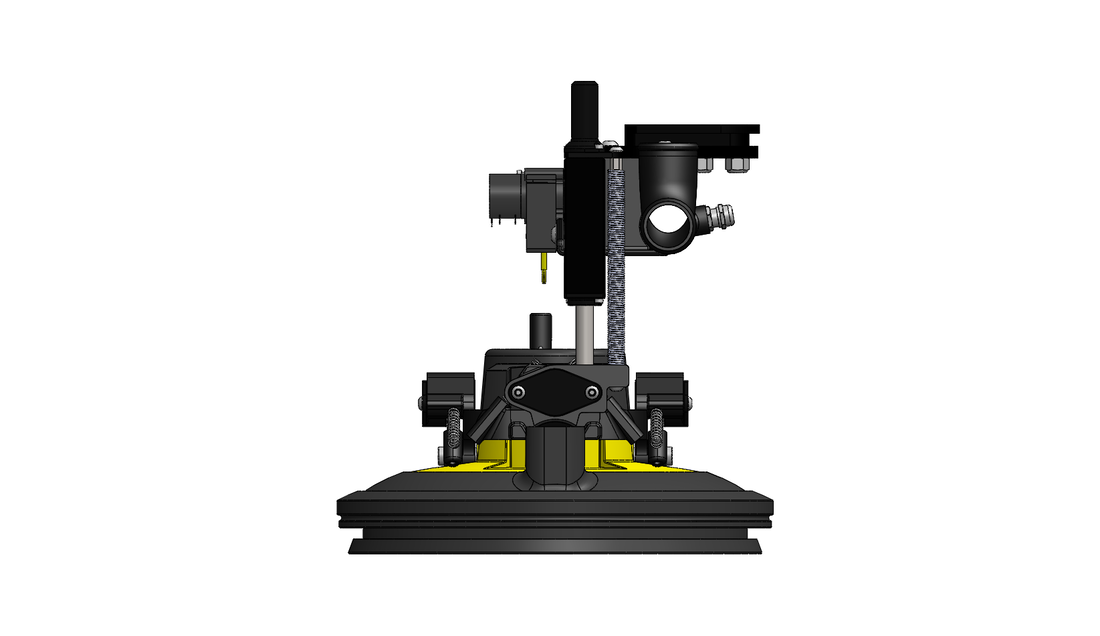
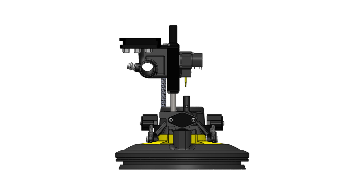
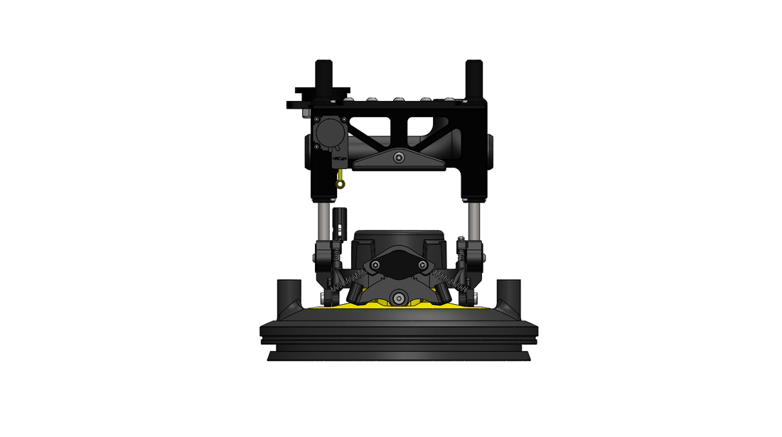
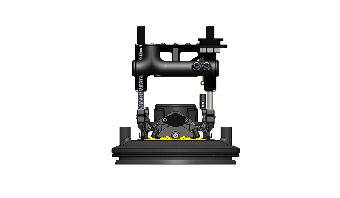
My goal with this project was to take the existing sanding head end effector and essentially perform DFM and DFA on it. This tool was attached to the end of a Universal Robot and used to sand drywall seams (for Level 4 finish) or the entire wall (Level 5 finish). The sanding head itself (UFO shaped part in yellow and black) is from a Mirka sanding pole, which is made for drywall finishing. Canvas took that part and added a custom gimbal with rotary dampers and springs (for a smooth finish). Compliance in the z-direction (in/out of the wall) was also necessary because during original testing, the UR arm couldn't relay force feedback quickly enough to move the sanding head closer/further from the wall in order to remove the specified amount of material (~0.3mm). Therefore, a set of linear rails were added, along with a long but weak compression spring, which kept a nearly constant force of 15N. A string potentiometer was also used to fake force feedback. Some magic on the software side converted the change in voltage of the string pot to force feedback, which could then be fed to the UR software. This, combined, with the compression spring, allowed for a smooth finish.
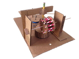
I originally wanted to redesign the entire compliance system, as I felt it was overly complicated and had a lot of small parts. My thought was to get rid of the gimbal and have three rods with three dampers and 3 springs, connected to a plastic ring around the sanding head via ball joint linkages. This would give z-compliance but also allow the head to conform to the wall.
This idea was nixed because the Process team (the people who set the specifications for material removal and surface finish) had already spent many days testing the current setup. Every spring was dialed just so in order to achieve the rate of removal and surface finish. That being decided, I then tried to keep the design as close to original as possible, while combining sub-assemblies into single parts.
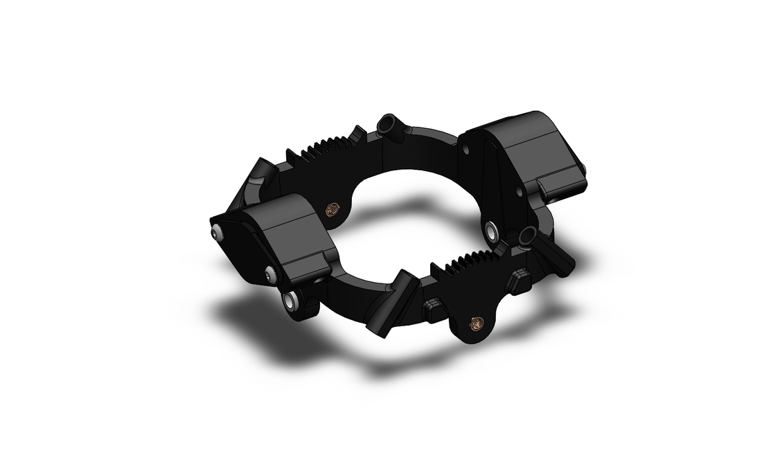
I combined the curved rack parts, which were originally made from aluminum and then fastened to another CNC'd aluminum part, into a single plastic part. There was too much slop between the curved rack and the pinion of the rotary damper, so I redesigned the gear teeth since the originally CAD model kept failing when I tried to edit dimensions. Essentially, anything that was a complex CNC'd aluminum part was converted to a glass filled nylon part. I also combined parts when I could. Lastly, I added a protective cover to the cable on the string potentiometer to prevent damage.